Universal Molding™
  • Table of Contents
    • I: Introduction
    • II: Parameters
    • III: Graphs
    • IV: Morphology
    • V: Aux. Equipment
    • VI: Calculations
    • VII: Rheology
    • VIII: Inj. Speed
    • IX: Fill Balance
    • X: Hold Stage
    • XI: Cooling Stage
    • XII: Process Limits
    • Appendices
  • questions or comments
  • FAQs
  • Buy our book!
    • MU™ English Version
    • MU™ Spanish Version
Universal Molding™
Español
Frequently Asked Questions
  • FAQs
Español
What’s different about Universal Molding™?

Some of the Universal Molding™ differences are:
At Universal Molding™, we pride ourselves on our innovative approach to injection molding. Our commitment to excellence has led us to develop several key differentiators that set us apart:

  1. Standardization: During optimization, we ensure that every setup is nearly identical. No longer does a good setup belong to just one individual. We’ve developed systematic procedures to ensure consistent setup parameters across all molders. Standardization is our goal.
  2. Molding from the Desk: Before even touching the equipment, mold, or material, we meticulously determine equipment sizing and initial parameters. This proactive approach streamlines the entire process.
  3. Machine Rheology: Our evaluation of flow behavior goes beyond traditional viscosity and shear rate equations. By utilizing injection time and peak power equations, we accurately describe the dynamics, resulting in up to a 70% reduction in injection time determination compared to other methods.
  4. Molding with Graphics: Our simplified method allows anyone, not just molders, to evaluate processes effectively. Quality control personnel find this tool invaluable.
  5. Accelerated Learning Curve: Our intensive training program transforms novices into precision molders within just three months. The results have exceeded expectations.
  6. Parameter Effects: We’ve dissected cause-and-effect relationships. For instance:
    • Mass Dimensions: These effects depend on material quantity and are manipulated during the holding stage.
    • Thermal Dimensions: Shrinkage-related effects come into play during the cooling stage.
  7. Molding Language: We communicate clearly, describing the impact of each parameter with simplicity and precision.
What percentage should be filled during the injection stage?

With Universal Molding™, we have adopted the practice of filling approximately 95% during the injection stage, including the weight of the runners. Let me explain the reasons behind this decision:

  1. Issues with 98% Filling: In the past, we recommended filling between 95% and 98%. However, we discovered that filling up to 98% caused some problems*. Beginners often thought that more was better and ended up facing issues such as flash, screw bounce, and limited pressure usage.
  2. Focus on Ideal Speed: During the injection stage, we aim to fill around 95% of the mold’s required volume within a defined injection time. Although we mold parts and not than runners, we consider the filling difficulty of the entire mold within an ideal injection time. This time encompasses everything from the recovery position to transfer, including both runners and parts.
  3. Benefits for Molders: We have consistently promoted the 95% filling approach, including runner weight, for over several years. The benefits have been significant for both novice and experienced molders.

Ultimately, each company can choose its approach based on experience and needs. Those who continue to fill between 95% and 98% without considering runner weight can continue doing so. However, for those starting in this field or managing a large number of molds, we recommend adopting Universal Molding™’s approach for equal or better results.

*Note: Some molds present an extreme difficulty in filling, for example, nylon ties which are long and thin, or micro-molding applications with narrow and awkward spaces for filling. In these cases, a filling percentage higher than 95% may be required.

What effect does a change in back pressure have?

A change in back pressure would influence discharge density, leading to variations in % of utilization, total volume % during the injection stage, and the cushion.
Example:

  1. Initial Values (Back pressure = 150 bar):
    • Recovery position = 51 mm
    • Transfer position = 9 mm
    • Shot weight = 15.8 g
    • Cushion = 8 mm
    • Volume % during injection:
    • % of Utilization:
    • Total volume:
    • Discharge density:
  2. Back pressure = 75 bar (same recovery and transfer positions):
    • Cushion = 7 mm
    • % Volume during injection:
    • Total Volume:
    • Discharge density:

Summary: By lowering the back pressure by half:

  • Cushion decreased by 1 mm.
  • Volume % during injection decreased by 2.3%.
  • % of Utilization increased by 1%.
  • Discharge density decreased by 0.02 g/cm³.

Note: The part weight did not change due to the change in back pressure because the mass was compensated by holding pressure (mass dimensions).

How significant is the discharge density?

The melt density in injection molding is a necessary value when determining screw positions; however, the value obtained from raw material suppliers can vary by over 20%. Thermoplastic melts are compressible, and their density is influenced by the pressure and temperature of the melt. During recovery, parameters such as back pressure and barrel zone temperatures affect melt density. Additionally, determining recovery positions becomes complicated if some melt passes to the other side of the check ring during fill. For this reason, Universal molders prefer discharge density.

Discharge Density:

  • Discharge density is more accurate when determining the recovery positions.
  • This density depends on several factors:
    • mass
    • volume
    • melt temperature
    • back pressure
    • melt leakage through the check ring during injection.

Calculation of Discharge Density:

  • Physically, we can determine discharge density if we know the injected volume and the total injected weight.
  • In an existing process, the injected volume is determined using the cylinder equation:
    • Volume = area × length
    • Area = (screw diameter)² × π/4
    • = recovery position – cushion position

Obtaining Discharge Density:

  • In an existing process, you can obtain the Recovery Position and Cushion Position by navigating through the control pages.
  • The injection weight is obtained by weighing the molded parts plus the runner (if it exists).
  • Finally, discharge density is calculated by dividing mass by volume:

What is the procedure for measuring melt temperature?

Variations in melt temperature can impact the molded product, including thermal dimensions (according to Universal MoldingTM) and plastic morphology. For this reason, it is crucial to verify the temperature using a standardized method or protocol.

Here are the key points:

  1. Barrel heat zones: These zones are used to obtain the most critical temperature: the melt temperature.
  2. Heating bands: The heating bands in the barrel zones, along with friction, are responsible for melting the material. Back pressure affects friction.
  3. Thermocouples in heat zones: Thermocouples measure the heat of the metal, not the melt.

Procedure:

  1. Ensure that the process has operated normally for at least ten cycles.
  2. Preheat an instrument to 25°C below the desired temperature. Digital “mini-blowers” are an economical option for preheating.
  3. Adjust the instrument to maintain the peak temperature value. This eliminates subjectivity when searching for the melt stabilization temperature.
  4. Stop the process (e.g., switch to semi-automatic mode). Once the mold opens, remove the injection unit and purge the melted material. You can do this on a removable surface for easy access.
  5. Immerse the instrument in the melt and agitate it. When you notice the temperature starting to drop, remove the instrument and record the peak temperature obtained. Follow all safety rules.

Note:

  • Use safety equipment such as uniforms, gloves, and goggles.
  • Adapt this protocol to your processes and ensure that everyone measures melt temperature in the same manner.

Is it necessary to adjust the process limits?

Injection molding process limits are necessary alarms and must always be set.

We have observed that many in the injection molding industry ignore the process limits. Some of these limits are the maximum injection pressure limit, the upper and lower cushion limits, and the recovery time limit. These alarms protect the equipment and the quality of the molded parts. Why are they ignored? Although some do it out of neglect, most operators ignore them because they do not know the consequences of not using them. Use these limits appropriately, and you will enjoy their benefits and savings.

What would cause the maximum injection pressure limit to be reached, and what could be its consequences?

It could be caused by a blocked cavity, either because a part was trapped in the cavity or a there was a plugged gate. If for some reason a cavity is clogged, the control has no way of knowing and will continue injecting, causing high injection pressures. These high pressures could cause flash in the parts, melt leaks into the hot runner system or melt leaks between the mold sprue bushing and the nozzle tip.

Another possibility could be that the recovery position was increased, causing excessive filling during the injection stage, significantly exceeding 95% of the mold’s capacity.

What would cause the lower cushion limit to be reached, and what could be its consequences?

Reaching the lower cushion limit is an indicator that the melt is leaking somewhere; it is typically the result of a dirty or defective check ring, and it could also be that it is leaking somewhere between the sprue bushing and the nozzle tip. This melt leak condition, if ignored for an extended time, could cause the melt to reach some of the barrel’s heater bands, to reach the wiring of the hot runner system, to sneak between mold actuators, in general, cause substantial damages. In addition, if the cushion position reaches zero (totally empty injection unit), it will nullify the hold stage, and part dimension changes could be observed.

What would cause the upper cushion limit to be reached, and what could be its consequences?

Reaching the upper cushion limit is an indicator of a blocked cavity or clogged gate. Also, if it's a hot-runner mold, it could be that a hot tip is clogged or damaged. The consequences could be over-packing of some of the parts, which could cause parts jamming in the cavity.

What would cause the recovery time limit to be reached, and what could be its consequences?

Reaching the recovery time limit could be caused by a lack of material. The melt in front of the check ring is what pushes the screw towards the recovery position, and if the resin feed is interrupted, the recovery time will be extended. Inconsistent resin flow may be due to the barrel heat affecting the feed throat, causing material agglomeration. This problem can arise for several reasons, such as an excessively high barrel temperature or poor cooling of the feed throat.

Systems that integrate pigment dosing in the throat of the injection unit could observe variation in the color of the parts. Do not forget that if the recovery time extends the cooling time, it could trigger an alarm in some machines.

What is an appropriate upper and lower limit for back pressure?

Before providing an opinion, let’s start with an overview. During recovery, the screw rotates, and the melt is pumped through the check valve toward the front of the screw. The accumulated melt at the front of the screw pushes it to the recovery position. Back pressure (BP) results from a controlled force opposing this displacement. The purpose of BP is to ensure consistently homogeneous melt (or improve dispersion of additives in the melt) and to increase or decrease shear rate during fill.

Changing back pressure has multiple consequences. For example, when increased:

  1. It enhances the mixing capacity of additives.
  2. Degradation of sensitive materials and fiber breakage increase.
  3. Screw and barrel wear intensifies.
  4. Heat contribution from friction increases, or heat contribution from heater bands decreases.
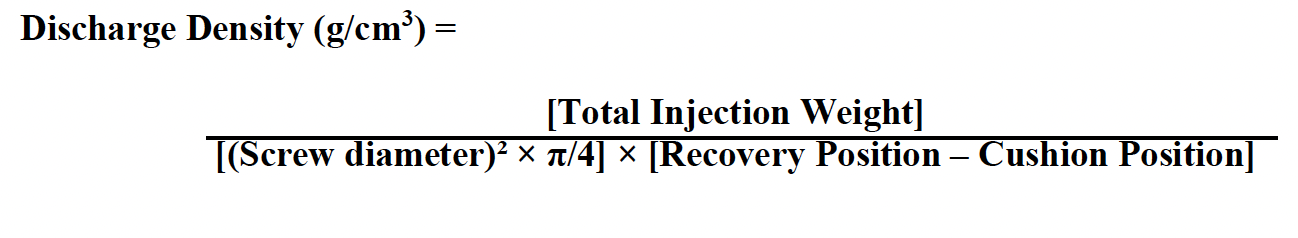
  5. The amount of melt increases; since molten thermoplastics are compressible, more plastic can be plasticized in the same volume. Consequently, more material is transferred to the mold during the injection stage.
  6. Melt viscosity typically decreases due to heat in the form of friction. As a result, machine rheology values change.

There are three typical options for BP limits:

  1. Fix BP without upper or lower limits.
  2. Establish BP limits within a validated range.
  3. No restrictions, allowing molders to decide.

Controlled industries (such as medical) usually work with one or two validated resins, often without regrind. Therefore, fixing BP without upper or lower limits is justified. If, for any reason, they need to use BP limits (due to regrind usage), they should set tight, validated BP limits and maintain a consistent virgin-to-regrind ratio.

However, this doesn’t mean that uncontrolled industries should have open BP adjustments or should leave them to the operator’s discretion. In uncontrolled industries where multiple resin brands are used for the same product and the virgin/regrind ratio is not controlled, it doesn’t make sense to establish narrow upper and lower BP limits.

Understand your material before setting BP limits. Ask yourself:

  1. Is the material fiber-filled?
  2. Does it degrade easily?
  3. Does the material supplier change based on market prices?
  4. Will additives like pigments or plasticizers be dosed?
  5. Does the virgin/regrind ratio change due to warehouse limitations?

For uncontrolled industries, allowing operators to manipulate back pressure should not be the option. Although melt index changes with material supplier and virgin/regrind ratio, a restricted upper and lower BP limit should be established and reviewed based on material changes.

Copyright Héctor Dilán.